| articolo-confronto-eng.pdf |
Pellis G., Di Cosmo F.
PHOTOGRAPHIC COMPARISON OF ARTICULATED JOINT
MODELS REPRODUCING THE MOVEMENT OF THE KNEE
16° Congresso Nazionale, Società Italiana di Artroscopia, Genova 2003
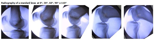
We wanted to assess the possible difference between the movement of the knee and the movement of the various brace joints normally used while dealing with knee traumas.
We based our remarks on the well known fact that the knee has a rotatory-translatory movement, as described by Smidt (1973), Fumagalli et al. (1977), Marinozzi and Pappalardo (1977), Kapandji (1977), Tittel (1979), Fleischmann and Line (1981), Nissel (1985), Insall (1986), Draganich et al. (1987), Yamaguchi and Zajac (1989), Melegatti (1997) and Steinbrück (1997).
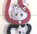
The thigh is considered the starting point and the extended leg the 0° angle (Fig. 1). According to articular mechanics, during the first 25-30° flexion the knee has a pure rotatory movement (Fig. 2). From 25° on (Fig. 3, 4 and 5), the rotation is combined with a gliding (forward) movement of the femoral condyles on the tibial flat bone that becomes more and more progressive and prevailing.
We considered also opinions opposite to the above, e.g. Loudon et al (1998), Putz (1995), Townsend Ind. Inc., patent no. EP 0361405A, (04.04.1990), Townsend, Jeffrey H., Williams Robert J., US patent no. WO 9215264° (17.09.92). They are based on the hypothesis that during the flexion-extension the knee has a translatory-rotatory ovement, i.e. the femur glides forward on the tibia for 8-9 mm (0-25°); the rotation phase follows from 25° on.
MATERIALS AND METHODS
In our research we reconstructed flat plastic models of the knee reproducing the outlines of femur and tibia with the average dimensions of adult bones. We chose four different kind of knee support joints and fixed them on the flat models.
MECHANICAL DESCRIPTION OF THE JOINTS
The joint used in a knee brace is formed by a mechanical articulation linked to two arms. We fixed the upper arm to the model femur and the lower arm to the model tibia.
|
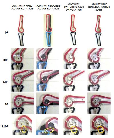
joint with fixed axis of rotation It consists of a pivot reproducing a rotatory movement around a central axis. During the flexion, the tibial brace is restrained and the femoral brace follows a circular trajectory around the pivot. |
|
joint with double axis of rotation The braces are in contact by means of their rounded, gear-wheel-shaped extremities with a pivot in their middle. When one brace turns around its own pivot, the other brace makes the same movement, in the opposite direction. During the flexion, the tibial brace is restrained and the femoral brace makes a so calledretrograde cycloid movement. |
|
|
joint with switching axes of rotation
It is composed of a plate linked to the upper brace. This plate has two grooves: a little central (transversal) one and a big peripheral (circular) one. Within each groove slides a pivot which is fixed to an external plate. During the first 25° flexion, the fulcrum is the pivot seated in the upper extremity of the circular groove. It makes the other pivot move forward the entire groove (8-9 mm linear translation), simulating the anterior glide of the femoral condyles on the tibial flat bone. In the second part of the flexion (from 25° to 120°) the fulcrum switches to the pivot seated in the lower extremity of the linear groove. The joint turns around it following the movement of the other pivot in the circular groove. The femoral brace has thus a translatory-rotatory movement. |
|
adjustable rotation radius joint
It is composed of two plates. One of them has two groves. The first little one goes from the middle of the plate linearly downward. The second one initially (from 0° to 30°) has a circular shape which lately becomes a spiral lightly going to the middle of the plate. The second plate has two pivots, one is seated in the linear groove and the other in the curvilinear one. Each plate is linked to the respective brace (femoral and tibial). During the flexion the joint causes a rotatory movement combined – after the first 30° – with a gliding due to the spiral shape of the groove rotatory-translatory movement. |
|
The initial axis of rotation
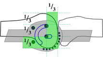
We took as a landmark common to all the joints – in order to uniform the position of the plastic models with respect to their mechanical joints – the initial axis of rotation located with the Nietert (1976) method.
We traced a line parallel to the tangent to the posterior outline of the femoral condyle and a line parallel to the tangent to its inferior outline at a distance equal to one third of the anteroposterior length of the femoral condyle. The intersection of those lines locates the initial axis of rotation.
In our models, this landmark has been applied to the joint with fixed axis, to the adjustable rotation radius joint (setting the initial position of the central pivot as initial centre) and to the joint with switching axes (setting the initial position of the central pivot as initial centre). We could not apply this landmark to the joint with double axis because the rotations around the two axes were always simultaneous.
The photographic documentation
We took a series of pictures of each model at the following angles of flexion: 0°, 30°, 60°, 90°, 110°.
We put standard distance markers on all models to highlight the possible differences between the trajectory of the natural movement shown by the radiographies and the movement determined by each joint.
RADIOGRAPHIC COMPARISON
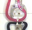
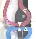
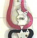
For a clearer comparison we traced the articular outlines of the models in the different positions and superimposed them to the respective radiographic outline (highlighted by the dark background).
For a clearer comparison we traced the articular outlines of the models in the different positions and superimposed them to the respective radiographic outline (highlighted by the dark background).
|
Difference between the radiographic outline and the joint with fixed axis. At the end of the flexion it can be noticed how the outline of the model moves forward and up. Recent studies fixed this up movement to an average value of 4,99 mm. |
|
|
|
Difference between the radiographic outline and the joint with double axis. At the end of the flexion the outline of the model is situated in a highly backward position. The femur of the model is lower than the tibial flat bone of the radiography. |
|
Difference between the radiographic outline and the joint with switched rotation. At the end of the flexion the model is in a highly forward and upward position respect to the radiographic outline. |
|
|
|
Difference between the radiographic outline and the adjustable rotation radius joint KTJ©. In all the phases of the flexion the model is situated in a position very similar to that of the radiographic outline. |
CONCLUSIONS
Our research clearly shows that the knee has a rotatory-translatory movement. After 30° of knee flexion the femoral condyle glides progressively forward on the tibial flat bone. This movement should be reproduced by all equipments or mechanical joints guiding the movement of the knee for physiotherapeutic reasons.
If the knee is restrained by a mechanical articulation that does not reproduce this kind of movement, the head of the bones tend to follow the trajectory of the mechanical articulation. This deviation produces tension in articular elements like the ligaments, particularly the cruciate ligaments, the capsule, the menisci and the cartilages.
Our research shows that the joint that better reproduces a movement respecting the order of the phases of rotation and gliding is the adjustable rotation radius joint.
The leg and its mechanical support move on parallel trajectories to allow a perfectly correspondent contact between leg and mechanical disposal during the entire movement.
This avoids all traction of the mechanical disposal on the articular structures and the beginning of tensions within the knee.
These are the main points of the Annex 1 to the Italian Legislative Decree No. 46 of February 24th, 1997 on the essential and general requirements for EC certifications:
1. Disposals must be designed and constructed so as not to prejudice the patient's clinical state and safety or the user safety and health;
2. During the disposal design and construction the manufacturer must observe all the safety measures, up-to-date with the technological progress.
